


Control Panel Checklist
Always perform the following tests in the order shown
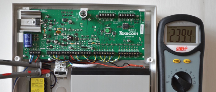
MAINS PHASE NEUTRAL TEST: AC voltage between live and neutral
This should measure between 220- 250VAC
MAINS PHASE EARTH TEST: AC voltage between live and earth
This should be the same as the previous reading
MAINS NEUTRAL EARTH TEST: AC voltage between neutral and earth
This reading should not exceed 1.2VAC
POWER SUPPLY CURRENT NORMAL TEST: AC current used by system when unset. Measure with meter in
series with the transformer output
POWER SUPPLY CURRENT IN ALARM TEST: AC current used by system when in alarm. Measure with meter in
series with the transformer output
INDUCED AC TEST: AC voltage between DC+ and earth. AC noise should not exceed 1.2volts max
BATTERY CHARGING VOLTAGE TEST: DC voltage at battery terminals. Measure with charge leads
connected to the battery
PANEL AUXILIARY DC VOLTAGE TEST:DC voltage supply to detectors. Should be within ±1 volt of the
battery charging voltage
BATTERY FLOAT CHARGE TEST: DC mA current flowing through battery. Should fall from a double mA
figure to a single mA figure within 30 seconds
BATTERY SYSTEM CURRENT NORMAL TEST:DC current used by system when unset. Ideally, not more than
five percent of the battery's Ah capacity
BATTERY SYSTEM CURRENT IN ALARM TEST:DC current used by system when in alarm. Ideally, not more
than ten percent of the battery's Ah capacity
BATTERY TEST: Record temperature, voltage and capacity available. Replace battery when reading falls
below 65% of Ah capacity
CIRCUIT RESISTANCE TESTS: Record all circuit resistances. Circuits must be removed from control
panel before testing
CIRCUIT EARTH LEAKAGE TEST: Check for resistance between zone,tamper and earth. Test with meter on
highest meg ohm range
BELL TAMPER RETURN TEST:Record resistance between 0 volt and removed tamper return. Check for
stable resistance.
PANEL ZONE WALK TEST:Walk test all detection zones to confirm operation. Check each circuit
operates normally, especially after lightning
SELF-ACTIVATING BELL TEST:Remove hold-off voltage to confirm operation. Replace if defective
BELL AND STROBE TEST: Activate bell and strobe to confirm operation. Replace if defective
COMMUNICATOR TEST: Activate communicator to confirm operation. Confirm correct operation with alarm
receiving centre
WIRING AND CONNECTIONS: Check panel for incorrect or loose wiring connections. Check all cables are
marked and connected correctly
VOLTAGE TEST: Check voltage at furthest detector is above 13VDC. Low or unstable DC
voltage at the detector is a main cause of false alarms
